
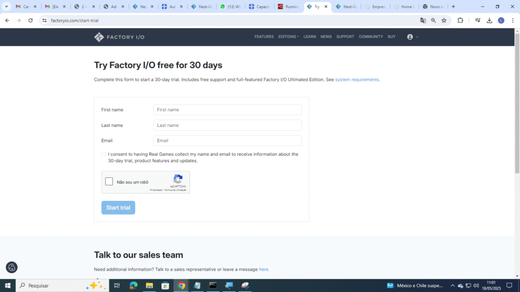
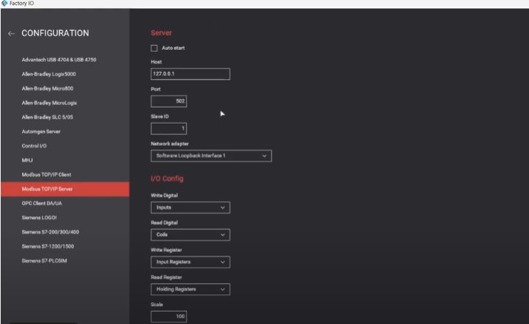
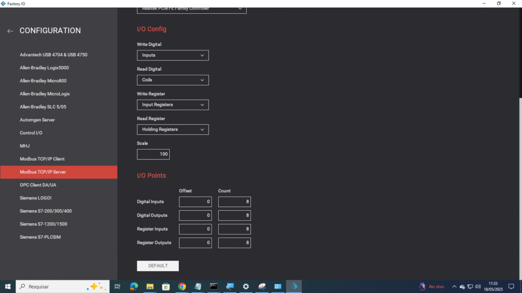
Nos tempos atuais, mais do que nunca plataformas de simulações em diversos seguimentos tem tomado conta do mercado nacional, e uma delas voltada a simular ambientes industriais (famoso "chão de fábrica") chama-se FactoryIO, disponível gratuitamente ao nível "trial" (teste) por 30 dias para download no seguinte endereço https://factoryio.com/. Nesse projeto iremos integrá-la com a plataforma Node-Red e nossa placa de desenvolvimento Arduino, tudo isso seguindo simples etapas!Com o conhecimento adquirido aqui, você poderá simular ambientes industriais, dando comandos vindos de um ambiente físico ou até mesmo retirar dados de sensores do ambiente virtual e trazê-los para seus dispositivos.
Para desenvolver este projeto, iremos precisar dos seguintes materiais e serviços:
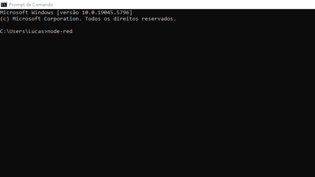
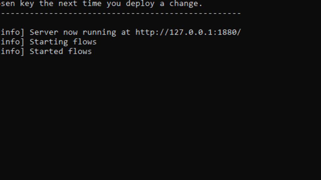
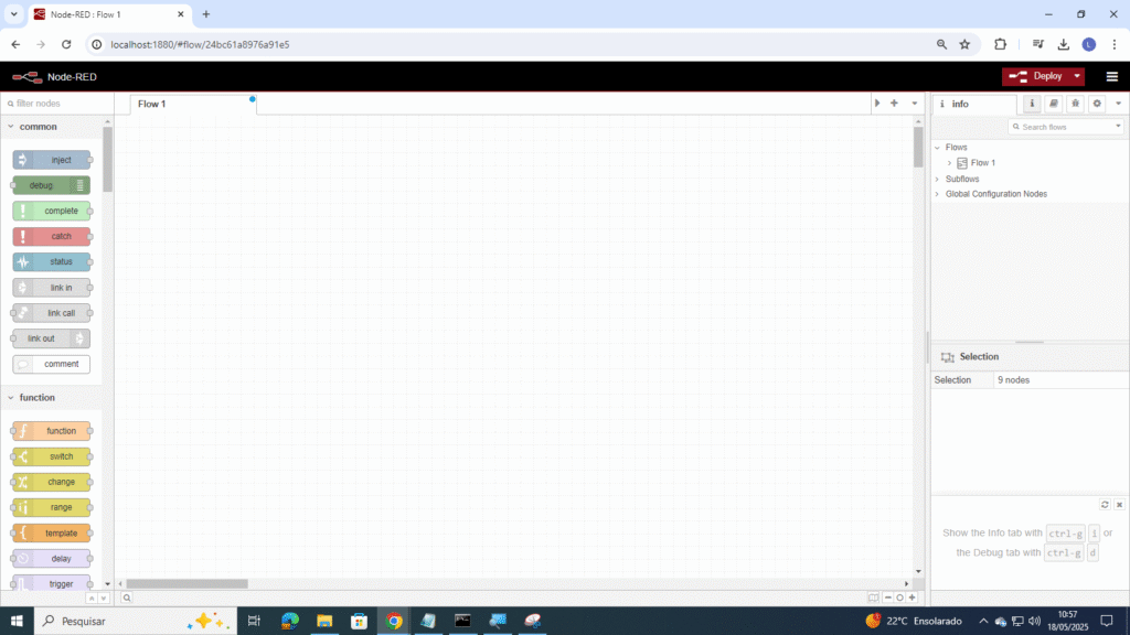
sudo npm install -g --unsafe-perm node-redObs.: Se você estiver usando o Windows, não inicie o comando com sudo.Esse comando instalará o Node-RED como um módulo global, juntamente com suas dependências.Após instalado, devemos abrir o Prompt de comandos (terminal) do sistema operacional para iniciá-lo com o comando:
node-red


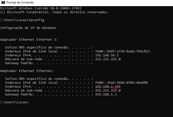
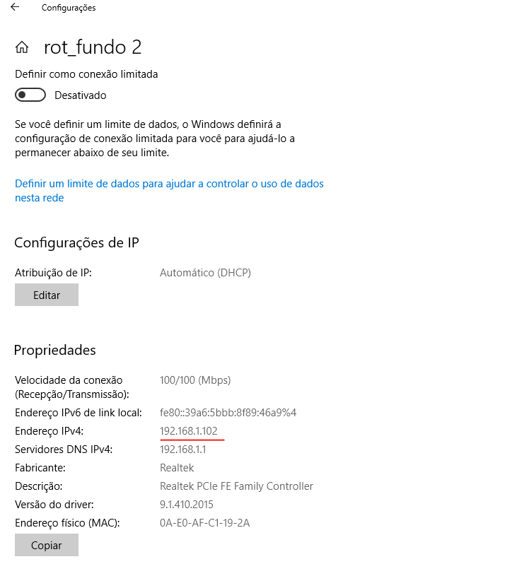
ip-config
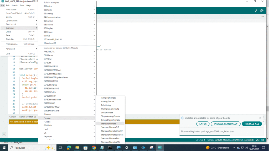
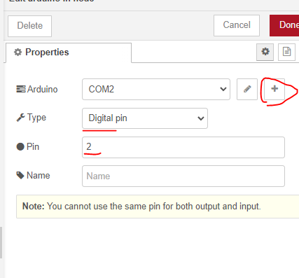
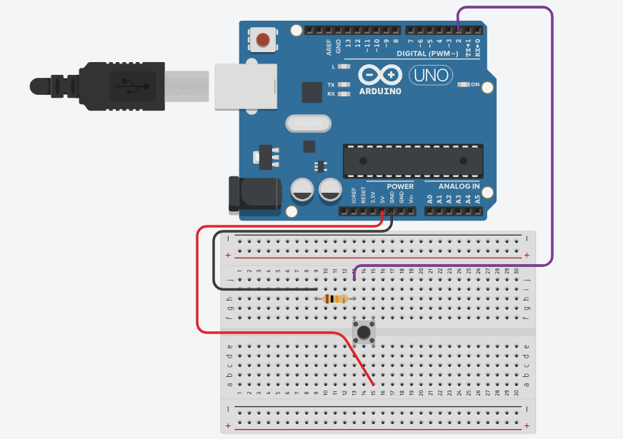
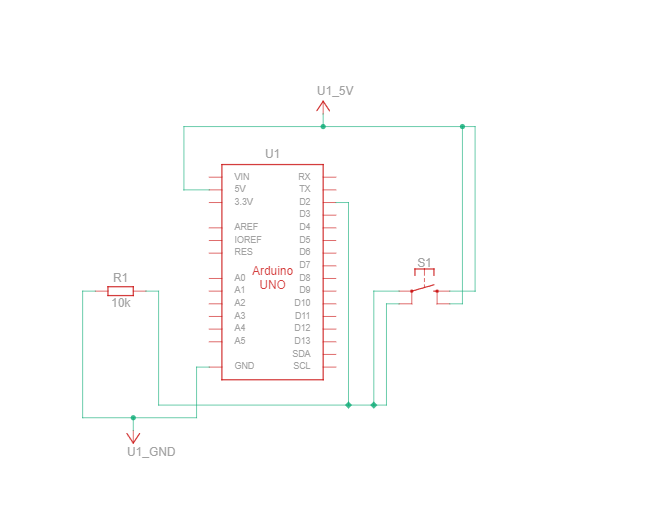
Não há necessidade de mudança no mesmo, pode ser utilizado o exemplo disponível na plataforma Arduino Ide conforme já mencionado.
/*
Firmata is a generic protocol for communicating with microcontrollers
from software on a host computer. It is intended to work with
any host computer software package.
To download a host software package, please click on the following link
to open the list of Firmata client libraries in your default browser.
https://github.com/firmata/arduino#firmata-client-libraries
Copyright (C) 2006-2008 Hans-Christoph Steiner. All rights reserved.
Copyright (C) 2010-2011 Paul Stoffregen. All rights reserved.
Copyright (C) 2009 Shigeru Kobayashi. All rights reserved.
Copyright (C) 2009-2016 Jeff Hoefs. All rights reserved.
This library is free software; you can redistribute it and/or
modify it under the terms of the GNU Lesser General Public
License as published by the Free Software Foundation; either
version 2.1 of the License, or (at your option) any later version.
See file LICENSE.txt for further informations on licensing terms.
Last updated August 17th, 2017
*/
#include <Servo.h>
#include <Wire.h>
#include <Firmata.h>
#define I2C_WRITE B00000000
#define I2C_READ B00001000
#define I2C_READ_CONTINUOUSLY B00010000
#define I2C_STOP_READING B00011000
#define I2C_READ_WRITE_MODE_MASK B00011000
#define I2C_10BIT_ADDRESS_MODE_MASK B00100000
#define I2C_END_TX_MASK B01000000
#define I2C_STOP_TX 1
#define I2C_RESTART_TX 0
#define I2C_MAX_QUERIES 8
#define I2C_REGISTER_NOT_SPECIFIED -1
// the minimum interval for sampling analog input
#define MINIMUM_SAMPLING_INTERVAL 1
/*==============================================================================
* GLOBAL VARIABLES
*============================================================================*/
#ifdef FIRMATA_SERIAL_FEATURE
SerialFirmata serialFeature;
#endif
/* analog inputs */
int analogInputsToReport = 0; // bitwise array to store pin reporting
/* digital input ports */
byte reportPINs[TOTAL_PORTS]; // 1 = report this port, 0 = silence
byte previousPINs[TOTAL_PORTS]; // previous 8 bits sent
/* pins configuration */
byte portConfigInputs[TOTAL_PORTS]; // each bit: 1 = pin in INPUT, 0 = anything else
/* timer variables */
unsigned long currentMillis; // store the current value from millis()
unsigned long previousMillis; // for comparison with currentMillis
unsigned int samplingInterval = 19; // how often to run the main loop (in ms)
/* i2c data */
struct i2c_device_info {
byte addr;
int reg;
byte bytes;
byte stopTX;
};
/* for i2c read continuous more */
i2c_device_info query[I2C_MAX_QUERIES];
byte i2cRxData[64];
boolean isI2CEnabled = false;
signed char queryIndex = -1;
// default delay time between i2c read request and Wire.requestFrom()
unsigned int i2cReadDelayTime = 0;
Servo servos[MAX_SERVOS];
byte servoPinMap[TOTAL_PINS];
byte detachedServos[MAX_SERVOS];
byte detachedServoCount = 0;
byte servoCount = 0;
boolean isResetting = false;
// Forward declare a few functions to avoid compiler errors with older versions
// of the Arduino IDE.
void setPinModeCallback(byte, int);
void reportAnalogCallback(byte analogPin, int value);
void sysexCallback(byte, byte, byte*);
/* utility functions */
void wireWrite(byte data)
{
#if ARDUINO >= 100
Wire.write((byte)data);
#else
Wire.send(data);
#endif
}
byte wireRead(void)
{
#if ARDUINO >= 100
return Wire.read();
#else
return Wire.receive();
#endif
}
/*==============================================================================
* FUNCTIONS
*============================================================================*/
void attachServo(byte pin, int minPulse, int maxPulse)
{
if (servoCount < MAX_SERVOS) {
// reuse indexes of detached servos until all have been reallocated
if (detachedServoCount > 0) {
servoPinMap[pin] = detachedServos[detachedServoCount - 1];
if (detachedServoCount > 0) detachedServoCount--;
} else {
servoPinMap[pin] = servoCount;
servoCount++;
}
if (minPulse > 0 && maxPulse > 0) {
servos[servoPinMap[pin]].attach(PIN_TO_DIGITAL(pin), minPulse, maxPulse);
} else {
servos[servoPinMap[pin]].attach(PIN_TO_DIGITAL(pin));
}
} else {
Firmata.sendString("Max servos attached");
}
}
void detachServo(byte pin)
{
servos[servoPinMap[pin]].detach();
// if we're detaching the last servo, decrement the count
// otherwise store the index of the detached servo
if (servoPinMap[pin] == servoCount && servoCount > 0) {
servoCount--;
} else if (servoCount > 0) {
// keep track of detached servos because we want to reuse their indexes
// before incrementing the count of attached servos
detachedServoCount++;
detachedServos[detachedServoCount - 1] = servoPinMap[pin];
}
servoPinMap[pin] = 255;
}
void enableI2CPins()
{
byte i;
// is there a faster way to do this? would probaby require importing
// Arduino.h to get SCL and SDA pins
for (i = 0; i < TOTAL_PINS; i++) {
if (IS_PIN_I2C(i)) {
// mark pins as i2c so they are ignore in non i2c data requests
setPinModeCallback(i, PIN_MODE_I2C);
}
}
isI2CEnabled = true;
Wire.begin();
}
/* disable the i2c pins so they can be used for other functions */
void disableI2CPins() {
isI2CEnabled = false;
// disable read continuous mode for all devices
queryIndex = -1;
}
void readAndReportData(byte address, int theRegister, byte numBytes, byte stopTX) {
// allow I2C requests that don't require a register read
// for example, some devices using an interrupt pin to signify new data available
// do not always require the register read so upon interrupt you call Wire.requestFrom()
if (theRegister != I2C_REGISTER_NOT_SPECIFIED) {
Wire.beginTransmission(address);
wireWrite((byte)theRegister);
Wire.endTransmission(stopTX); // default = true
// do not set a value of 0
if (i2cReadDelayTime > 0) {
// delay is necessary for some devices such as WiiNunchuck
delayMicroseconds(i2cReadDelayTime);
}
} else {
theRegister = 0; // fill the register with a dummy value
}
Wire.requestFrom(address, numBytes); // all bytes are returned in requestFrom
// check to be sure correct number of bytes were returned by slave
if (numBytes < Wire.available()) {
Firmata.sendString("I2C: Too many bytes received");
} else if (numBytes > Wire.available()) {
Firmata.sendString("I2C: Too few bytes received");
numBytes = Wire.available();
}
i2cRxData[0] = address;
i2cRxData[1] = theRegister;
for (int i = 0; i < numBytes && Wire.available(); i++) {
i2cRxData[2 + i] = wireRead();
}
// send slave address, register and received bytes
Firmata.sendSysex(SYSEX_I2C_REPLY, numBytes + 2, i2cRxData);
}
void outputPort(byte portNumber, byte portValue, byte forceSend)
{
// pins not configured as INPUT are cleared to zeros
portValue = portValue & portConfigInputs[portNumber];
// only send if the value is different than previously sent
if (forceSend || previousPINs[portNumber] != portValue) {
Firmata.sendDigitalPort(portNumber, portValue);
previousPINs[portNumber] = portValue;
}
}
/* -----------------------------------------------------------------------------
* check all the active digital inputs for change of state, then add any events
* to the Serial output queue using Serial.print() */
void checkDigitalInputs(void)
{
/* Using non-looping code allows constants to be given to readPort().
* The compiler will apply substantial optimizations if the inputs
* to readPort() are compile-time constants. */
if (TOTAL_PORTS > 0 && reportPINs[0]) outputPort(0, readPort(0, portConfigInputs[0]), false);
if (TOTAL_PORTS > 1 && reportPINs[1]) outputPort(1, readPort(1, portConfigInputs[1]), false);
if (TOTAL_PORTS > 2 && reportPINs[2]) outputPort(2, readPort(2, portConfigInputs[2]), false);
if (TOTAL_PORTS > 3 && reportPINs[3]) outputPort(3, readPort(3, portConfigInputs[3]), false);
if (TOTAL_PORTS > 4 && reportPINs[4]) outputPort(4, readPort(4, portConfigInputs[4]), false);
if (TOTAL_PORTS > 5 && reportPINs[5]) outputPort(5, readPort(5, portConfigInputs[5]), false);
if (TOTAL_PORTS > 6 && reportPINs[6]) outputPort(6, readPort(6, portConfigInputs[6]), false);
if (TOTAL_PORTS > 7 && reportPINs[7]) outputPort(7, readPort(7, portConfigInputs[7]), false);
if (TOTAL_PORTS > 8 && reportPINs[8]) outputPort(8, readPort(8, portConfigInputs[8]), false);
if (TOTAL_PORTS > 9 && reportPINs[9]) outputPort(9, readPort(9, portConfigInputs[9]), false);
if (TOTAL_PORTS > 10 && reportPINs[10]) outputPort(10, readPort(10, portConfigInputs[10]), false);
if (TOTAL_PORTS > 11 && reportPINs[11]) outputPort(11, readPort(11, portConfigInputs[11]), false);
if (TOTAL_PORTS > 12 && reportPINs[12]) outputPort(12, readPort(12, portConfigInputs[12]), false);
if (TOTAL_PORTS > 13 && reportPINs[13]) outputPort(13, readPort(13, portConfigInputs[13]), false);
if (TOTAL_PORTS > 14 && reportPINs[14]) outputPort(14, readPort(14, portConfigInputs[14]), false);
if (TOTAL_PORTS > 15 && reportPINs[15]) outputPort(15, readPort(15, portConfigInputs[15]), false);
}
// -----------------------------------------------------------------------------
/* sets the pin mode to the correct state and sets the relevant bits in the
* two bit-arrays that track Digital I/O and PWM status
*/
void setPinModeCallback(byte pin, int mode)
{
if (Firmata.getPinMode(pin) == PIN_MODE_IGNORE)
return;
if (Firmata.getPinMode(pin) == PIN_MODE_I2C && isI2CEnabled && mode != PIN_MODE_I2C) {
// disable i2c so pins can be used for other functions
// the following if statements should reconfigure the pins properly
disableI2CPins();
}
if (IS_PIN_DIGITAL(pin) && mode != PIN_MODE_SERVO) {
if (servoPinMap[pin] < MAX_SERVOS && servos[servoPinMap[pin]].attached()) {
detachServo(pin);
}
}
if (IS_PIN_ANALOG(pin)) {
reportAnalogCallback(PIN_TO_ANALOG(pin), mode == PIN_MODE_ANALOG ? 1 : 0); // turn on/off reporting
}
if (IS_PIN_DIGITAL(pin)) {
if (mode == INPUT || mode == PIN_MODE_PULLUP) {
portConfigInputs[pin / 8] |= (1 << (pin & 7));
} else {
portConfigInputs[pin / 8] &= ~(1 << (pin & 7));
}
}
Firmata.setPinState(pin, 0);
switch (mode) {
case PIN_MODE_ANALOG:
if (IS_PIN_ANALOG(pin)) {
if (IS_PIN_DIGITAL(pin)) {
pinMode(PIN_TO_DIGITAL(pin), INPUT); // disable output driver
#if ARDUINO <= 100
// deprecated since Arduino 1.0.1 - TODO: drop support in Firmata 2.6
digitalWrite(PIN_TO_DIGITAL(pin), LOW); // disable internal pull-ups
#endif
}
Firmata.setPinMode(pin, PIN_MODE_ANALOG);
}
break;
case INPUT:
if (IS_PIN_DIGITAL(pin)) {
pinMode(PIN_TO_DIGITAL(pin), INPUT); // disable output driver
#if ARDUINO <= 100
// deprecated since Arduino 1.0.1 - TODO: drop support in Firmata 2.6
digitalWrite(PIN_TO_DIGITAL(pin), LOW); // disable internal pull-ups
#endif
Firmata.setPinMode(pin, INPUT);
}
break;
case PIN_MODE_PULLUP:
if (IS_PIN_DIGITAL(pin)) {
pinMode(PIN_TO_DIGITAL(pin), INPUT_PULLUP);
Firmata.setPinMode(pin, PIN_MODE_PULLUP);
Firmata.setPinState(pin, 1);
}
break;
case OUTPUT:
if (IS_PIN_DIGITAL(pin)) {
if (Firmata.getPinMode(pin) == PIN_MODE_PWM) {
// Disable PWM if pin mode was previously set to PWM.
digitalWrite(PIN_TO_DIGITAL(pin), LOW);
}
pinMode(PIN_TO_DIGITAL(pin), OUTPUT);
Firmata.setPinMode(pin, OUTPUT);
}
break;
case PIN_MODE_PWM:
if (IS_PIN_PWM(pin)) {
pinMode(PIN_TO_PWM(pin), OUTPUT);
analogWrite(PIN_TO_PWM(pin), 0);
Firmata.setPinMode(pin, PIN_MODE_PWM);
}
break;
case PIN_MODE_SERVO:
if (IS_PIN_DIGITAL(pin)) {
Firmata.setPinMode(pin, PIN_MODE_SERVO);
if (servoPinMap[pin] == 255 || !servos[servoPinMap[pin]].attached()) {
// pass -1 for min and max pulse values to use default values set
// by Servo library
attachServo(pin, -1, -1);
}
}
break;
case PIN_MODE_I2C:
if (IS_PIN_I2C(pin)) {
// mark the pin as i2c
// the user must call I2C_CONFIG to enable I2C for a device
Firmata.setPinMode(pin, PIN_MODE_I2C);
}
break;
case PIN_MODE_SERIAL:
#ifdef FIRMATA_SERIAL_FEATURE
serialFeature.handlePinMode(pin, PIN_MODE_SERIAL);
#endif
break;
default:
Firmata.sendString("Unknown pin mode"); // TODO: put error msgs in EEPROM
}
// TODO: save status to EEPROM here, if changed
}
/*
* Sets the value of an individual pin. Useful if you want to set a pin value but
* are not tracking the digital port state.
* Can only be used on pins configured as OUTPUT.
* Cannot be used to enable pull-ups on Digital INPUT pins.
*/
void setPinValueCallback(byte pin, int value)
{
if (pin < TOTAL_PINS && IS_PIN_DIGITAL(pin)) {
if (Firmata.getPinMode(pin) == OUTPUT) {
Firmata.setPinState(pin, value);
digitalWrite(PIN_TO_DIGITAL(pin), value);
}
}
}
void analogWriteCallback(byte pin, int value)
{
if (pin < TOTAL_PINS) {
switch (Firmata.getPinMode(pin)) {
case PIN_MODE_SERVO:
if (IS_PIN_DIGITAL(pin))
servos[servoPinMap[pin]].write(value);
Firmata.setPinState(pin, value);
break;
case PIN_MODE_PWM:
if (IS_PIN_PWM(pin))
analogWrite(PIN_TO_PWM(pin), value);
Firmata.setPinState(pin, value);
break;
}
}
}
void digitalWriteCallback(byte port, int value)
{
byte pin, lastPin, pinValue, mask = 1, pinWriteMask = 0;
if (port < TOTAL_PORTS) {
// create a mask of the pins on this port that are writable.
lastPin = port * 8 + 8;
if (lastPin > TOTAL_PINS) lastPin = TOTAL_PINS;
for (pin = port * 8; pin < lastPin; pin++) {
// do not disturb non-digital pins (eg, Rx & Tx)
if (IS_PIN_DIGITAL(pin)) {
// do not touch pins in PWM, ANALOG, SERVO or other modes
if (Firmata.getPinMode(pin) == OUTPUT || Firmata.getPinMode(pin) == INPUT) {
pinValue = ((byte)value & mask) ? 1 : 0;
if (Firmata.getPinMode(pin) == OUTPUT) {
pinWriteMask |= mask;
} else if (Firmata.getPinMode(pin) == INPUT && pinValue == 1 && Firmata.getPinState(pin) != 1) {
// only handle INPUT here for backwards compatibility
#if ARDUINO > 100
pinMode(pin, INPUT_PULLUP);
#else
// only write to the INPUT pin to enable pullups if Arduino v1.0.0 or earlier
pinWriteMask |= mask;
#endif
}
Firmata.setPinState(pin, pinValue);
}
}
mask = mask << 1;
}
writePort(port, (byte)value, pinWriteMask);
}
}
// -----------------------------------------------------------------------------
/* sets bits in a bit array (int) to toggle the reporting of the analogIns
*/
//void FirmataClass::setAnalogPinReporting(byte pin, byte state) {
//}
void reportAnalogCallback(byte analogPin, int value)
{
if (analogPin < TOTAL_ANALOG_PINS) {
if (value == 0) {
analogInputsToReport = analogInputsToReport & ~ (1 << analogPin);
} else {
analogInputsToReport = analogInputsToReport | (1 << analogPin);
// prevent during system reset or all analog pin values will be reported
// which may report noise for unconnected analog pins
if (!isResetting) {
// Send pin value immediately. This is helpful when connected via
// ethernet, wi-fi or bluetooth so pin states can be known upon
// reconnecting.
Firmata.sendAnalog(analogPin, analogRead(analogPin));
}
}
}
// TODO: save status to EEPROM here, if changed
}
void reportDigitalCallback(byte port, int value)
{
if (port < TOTAL_PORTS) {
reportPINs[port] = (byte)value;
// Send port value immediately. This is helpful when connected via
// ethernet, wi-fi or bluetooth so pin states can be known upon
// reconnecting.
if (value) outputPort(port, readPort(port, portConfigInputs[port]), true);
}
// do not disable analog reporting on these 8 pins, to allow some
// pins used for digital, others analog. Instead, allow both types
// of reporting to be enabled, but check if the pin is configured
// as analog when sampling the analog inputs. Likewise, while
// scanning digital pins, portConfigInputs will mask off values from any
// pins configured as analog
}
/*==============================================================================
* SYSEX-BASED commands
*============================================================================*/
void sysexCallback(byte command, byte argc, byte *argv)
{
byte mode;
byte stopTX;
byte slaveAddress;
byte data;
int slaveRegister;
unsigned int delayTime;
switch (command) {
case I2C_REQUEST:
mode = argv[1] & I2C_READ_WRITE_MODE_MASK;
if (argv[1] & I2C_10BIT_ADDRESS_MODE_MASK) {
Firmata.sendString("10-bit addressing not supported");
return;
}
else {
slaveAddress = argv[0];
}
// need to invert the logic here since 0 will be default for client
// libraries that have not updated to add support for restart tx
if (argv[1] & I2C_END_TX_MASK) {
stopTX = I2C_RESTART_TX;
}
else {
stopTX = I2C_STOP_TX; // default
}
switch (mode) {
case I2C_WRITE:
Wire.beginTransmission(slaveAddress);
for (byte i = 2; i < argc; i += 2) {
data = argv[i] + (argv[i + 1] << 7);
wireWrite(data);
}
Wire.endTransmission();
delayMicroseconds(70);
break;
case I2C_READ:
if (argc == 6) {
// a slave register is specified
slaveRegister = argv[2] + (argv[3] << 7);
data = argv[4] + (argv[5] << 7); // bytes to read
}
else {
// a slave register is NOT specified
slaveRegister = I2C_REGISTER_NOT_SPECIFIED;
data = argv[2] + (argv[3] << 7); // bytes to read
}
readAndReportData(slaveAddress, (int)slaveRegister, data, stopTX);
break;
case I2C_READ_CONTINUOUSLY:
if ((queryIndex + 1) >= I2C_MAX_QUERIES) {
// too many queries, just ignore
Firmata.sendString("too many queries");
break;
}
if (argc == 6) {
// a slave register is specified
slaveRegister = argv[2] + (argv[3] << 7);
data = argv[4] + (argv[5] << 7); // bytes to read
}
else {
// a slave register is NOT specified
slaveRegister = (int)I2C_REGISTER_NOT_SPECIFIED;
data = argv[2] + (argv[3] << 7); // bytes to read
}
queryIndex++;
query[queryIndex].addr = slaveAddress;
query[queryIndex].reg = slaveRegister;
query[queryIndex].bytes = data;
query[queryIndex].stopTX = stopTX;
break;
case I2C_STOP_READING:
byte queryIndexToSkip;
// if read continuous mode is enabled for only 1 i2c device, disable
// read continuous reporting for that device
if (queryIndex <= 0) {
queryIndex = -1;
} else {
queryIndexToSkip = 0;
// if read continuous mode is enabled for multiple devices,
// determine which device to stop reading and remove it's data from
// the array, shifiting other array data to fill the space
for (byte i = 0; i < queryIndex + 1; i++) {
if (query[i].addr == slaveAddress) {
queryIndexToSkip = i;
break;
}
}
for (byte i = queryIndexToSkip; i < queryIndex + 1; i++) {
if (i < I2C_MAX_QUERIES) {
query[i].addr = query[i + 1].addr;
query[i].reg = query[i + 1].reg;
query[i].bytes = query[i + 1].bytes;
query[i].stopTX = query[i + 1].stopTX;
}
}
queryIndex--;
}
break;
default:
break;
}
break;
case I2C_CONFIG:
delayTime = (argv[0] + (argv[1] << 7));
if (argc > 1 && delayTime > 0) {
i2cReadDelayTime = delayTime;
}
if (!isI2CEnabled) {
enableI2CPins();
}
break;
case SERVO_CONFIG:
if (argc > 4) {
// these vars are here for clarity, they'll optimized away by the compiler
byte pin = argv[0];
int minPulse = argv[1] + (argv[2] << 7);
int maxPulse = argv[3] + (argv[4] << 7);
if (IS_PIN_DIGITAL(pin)) {
if (servoPinMap[pin] < MAX_SERVOS && servos[servoPinMap[pin]].attached()) {
detachServo(pin);
}
attachServo(pin, minPulse, maxPulse);
setPinModeCallback(pin, PIN_MODE_SERVO);
}
}
break;
case SAMPLING_INTERVAL:
if (argc > 1) {
samplingInterval = argv[0] + (argv[1] << 7);
if (samplingInterval < MINIMUM_SAMPLING_INTERVAL) {
samplingInterval = MINIMUM_SAMPLING_INTERVAL;
}
} else {
//Firmata.sendString("Not enough data");
}
break;
case EXTENDED_ANALOG:
if (argc > 1) {
int val = argv[1];
if (argc > 2) val |= (argv[2] << 7);
if (argc > 3) val |= (argv[3] << 14);
analogWriteCallback(argv[0], val);
}
break;
case CAPABILITY_QUERY:
Firmata.write(START_SYSEX);
Firmata.write(CAPABILITY_RESPONSE);
for (byte pin = 0; pin < TOTAL_PINS; pin++) {
if (IS_PIN_DIGITAL(pin)) {
Firmata.write((byte)INPUT);
Firmata.write(1);
Firmata.write((byte)PIN_MODE_PULLUP);
Firmata.write(1);
Firmata.write((byte)OUTPUT);
Firmata.write(1);
}
if (IS_PIN_ANALOG(pin)) {
Firmata.write(PIN_MODE_ANALOG);
Firmata.write(10); // 10 = 10-bit resolution
}
if (IS_PIN_PWM(pin)) {
Firmata.write(PIN_MODE_PWM);
Firmata.write(DEFAULT_PWM_RESOLUTION);
}
if (IS_PIN_DIGITAL(pin)) {
Firmata.write(PIN_MODE_SERVO);
Firmata.write(14);
}
if (IS_PIN_I2C(pin)) {
Firmata.write(PIN_MODE_I2C);
Firmata.write(1); // TODO: could assign a number to map to SCL or SDA
}
#ifdef FIRMATA_SERIAL_FEATURE
serialFeature.handleCapability(pin);
#endif
Firmata.write(127);
}
Firmata.write(END_SYSEX);
break;
case PIN_STATE_QUERY:
if (argc > 0) {
byte pin = argv[0];
Firmata.write(START_SYSEX);
Firmata.write(PIN_STATE_RESPONSE);
Firmata.write(pin);
if (pin < TOTAL_PINS) {
Firmata.write(Firmata.getPinMode(pin));
Firmata.write((byte)Firmata.getPinState(pin) & 0x7F);
if (Firmata.getPinState(pin) & 0xFF80) Firmata.write((byte)(Firmata.getPinState(pin) >> 7) & 0x7F);
if (Firmata.getPinState(pin) & 0xC000) Firmata.write((byte)(Firmata.getPinState(pin) >> 14) & 0x7F);
}
Firmata.write(END_SYSEX);
}
break;
case ANALOG_MAPPING_QUERY:
Firmata.write(START_SYSEX);
Firmata.write(ANALOG_MAPPING_RESPONSE);
for (byte pin = 0; pin < TOTAL_PINS; pin++) {
Firmata.write(IS_PIN_ANALOG(pin) ? PIN_TO_ANALOG(pin) : 127);
}
Firmata.write(END_SYSEX);
break;
case SERIAL_MESSAGE:
#ifdef FIRMATA_SERIAL_FEATURE
serialFeature.handleSysex(command, argc, argv);
#endif
break;
}
}
/*==============================================================================
* SETUP()
*============================================================================*/
void systemResetCallback()
{
isResetting = true;
// initialize a defalt state
// TODO: option to load config from EEPROM instead of default
#ifdef FIRMATA_SERIAL_FEATURE
serialFeature.reset();
#endif
if (isI2CEnabled) {
disableI2CPins();
}
for (byte i = 0; i < TOTAL_PORTS; i++) {
reportPINs[i] = false; // by default, reporting off
portConfigInputs[i] = 0; // until activated
previousPINs[i] = 0;
}
for (byte i = 0; i < TOTAL_PINS; i++) {
// pins with analog capability default to analog input
// otherwise, pins default to digital output
if (IS_PIN_ANALOG(i)) {
// turns off pullup, configures everything
setPinModeCallback(i, PIN_MODE_ANALOG);
} else if (IS_PIN_DIGITAL(i)) {
// sets the output to 0, configures portConfigInputs
setPinModeCallback(i, OUTPUT);
}
servoPinMap[i] = 255;
}
// by default, do not report any analog inputs
analogInputsToReport = 0;
detachedServoCount = 0;
servoCount = 0;
/* send digital inputs to set the initial state on the host computer,
* since once in the loop(), this firmware will only send on change */
/*
TODO: this can never execute, since no pins default to digital input
but it will be needed when/if we support EEPROM stored config
for (byte i=0; i < TOTAL_PORTS; i++) {
outputPort(i, readPort(i, portConfigInputs[i]), true);
}
*/
isResetting = false;
}
void setup()
{
Firmata.setFirmwareVersion(FIRMATA_FIRMWARE_MAJOR_VERSION, FIRMATA_FIRMWARE_MINOR_VERSION);
Firmata.attach(ANALOG_MESSAGE, analogWriteCallback);
Firmata.attach(DIGITAL_MESSAGE, digitalWriteCallback);
Firmata.attach(REPORT_ANALOG, reportAnalogCallback);
Firmata.attach(REPORT_DIGITAL, reportDigitalCallback);
Firmata.attach(SET_PIN_MODE, setPinModeCallback);
Firmata.attach(SET_DIGITAL_PIN_VALUE, setPinValueCallback);
Firmata.attach(START_SYSEX, sysexCallback);
Firmata.attach(SYSTEM_RESET, systemResetCallback);
// to use a port other than Serial, such as Serial1 on an Arduino Leonardo or Mega,
// Call begin(baud) on the alternate serial port and pass it to Firmata to begin like this:
// Serial1.begin(57600);
// Firmata.begin(Serial1);
// However do not do this if you are using SERIAL_MESSAGE
Firmata.begin(57600);
while (!Serial) {
; // wait for serial port to connect. Needed for ATmega32u4-based boards and Arduino 101
}
systemResetCallback(); // reset to default config
}
/*==============================================================================
* LOOP()
*============================================================================*/
void loop()
{
byte pin, analogPin;
/* DIGITALREAD - as fast as possible, check for changes and output them to the
* FTDI buffer using Serial.print() */
checkDigitalInputs();
/* STREAMREAD - processing incoming messagse as soon as possible, while still
* checking digital inputs. */
while (Firmata.available())
Firmata.processInput();
// TODO - ensure that Stream buffer doesn't go over 60 bytes
currentMillis = millis();
if (currentMillis - previousMillis > samplingInterval) {
previousMillis += samplingInterval;
/* ANALOGREAD - do all analogReads() at the configured sampling interval */
for (pin = 0; pin < TOTAL_PINS; pin++) {
if (IS_PIN_ANALOG(pin) && Firmata.getPinMode(pin) == PIN_MODE_ANALOG) {
analogPin = PIN_TO_ANALOG(pin);
if (analogInputsToReport & (1 << analogPin)) {
Firmata.sendAnalog(analogPin, analogRead(analogPin));
}
}
}
// report i2c data for all device with read continuous mode enabled
if (queryIndex > -1) {
for (byte i = 0; i < queryIndex + 1; i++) {
readAndReportData(query[i].addr, query[i].reg, query[i].bytes, query[i].stopTX);
}
}
}
#ifdef FIRMATA_SERIAL_FEATURE
serialFeature.update();
#endif
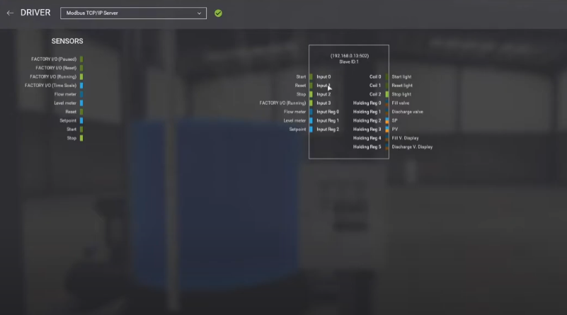
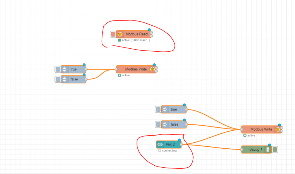
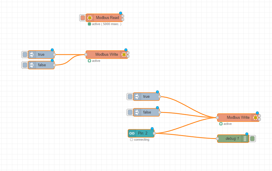
}Então, com tudo finalmente concluído, você pode dar comandos aos seus dispositivos no FactoryIO a partir de seu Arduino:
|